
1. Key Switch Operated
An integral time switch is provided so that timed automatic control of gas installations may be achieved. For security, the system is key switch operated and is provided with its own emergency shut off switch. Additional safety features such as remote emergency cut off switches, fire switches and thermal fuses can be included in any scheme.
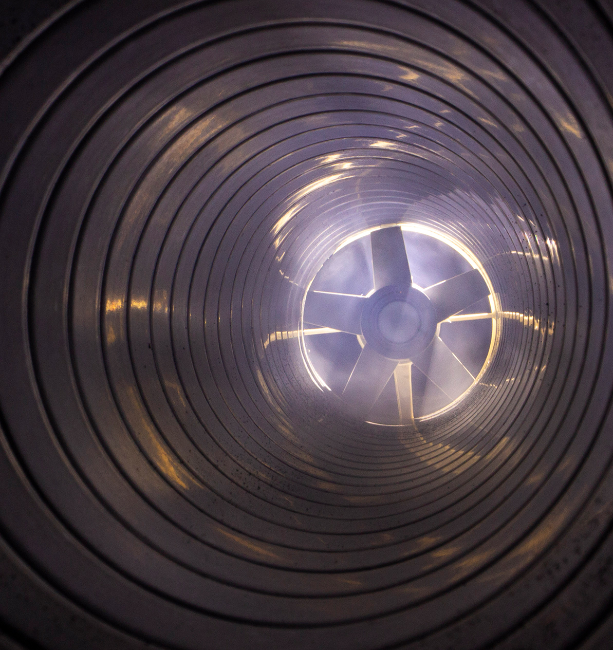
2. Interlocking ventilation
The ProvenGas safety system interlocks any mechanical ventilation with the gas supply so that the gas can only be used when all the fans are working. It also incorporates gas proving, ensuring that all equipment is off before allowing any gas to be used.
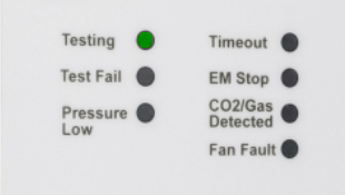
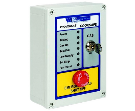
3. Electrical Control Panel
LED indicators on the panel show the status of the system.
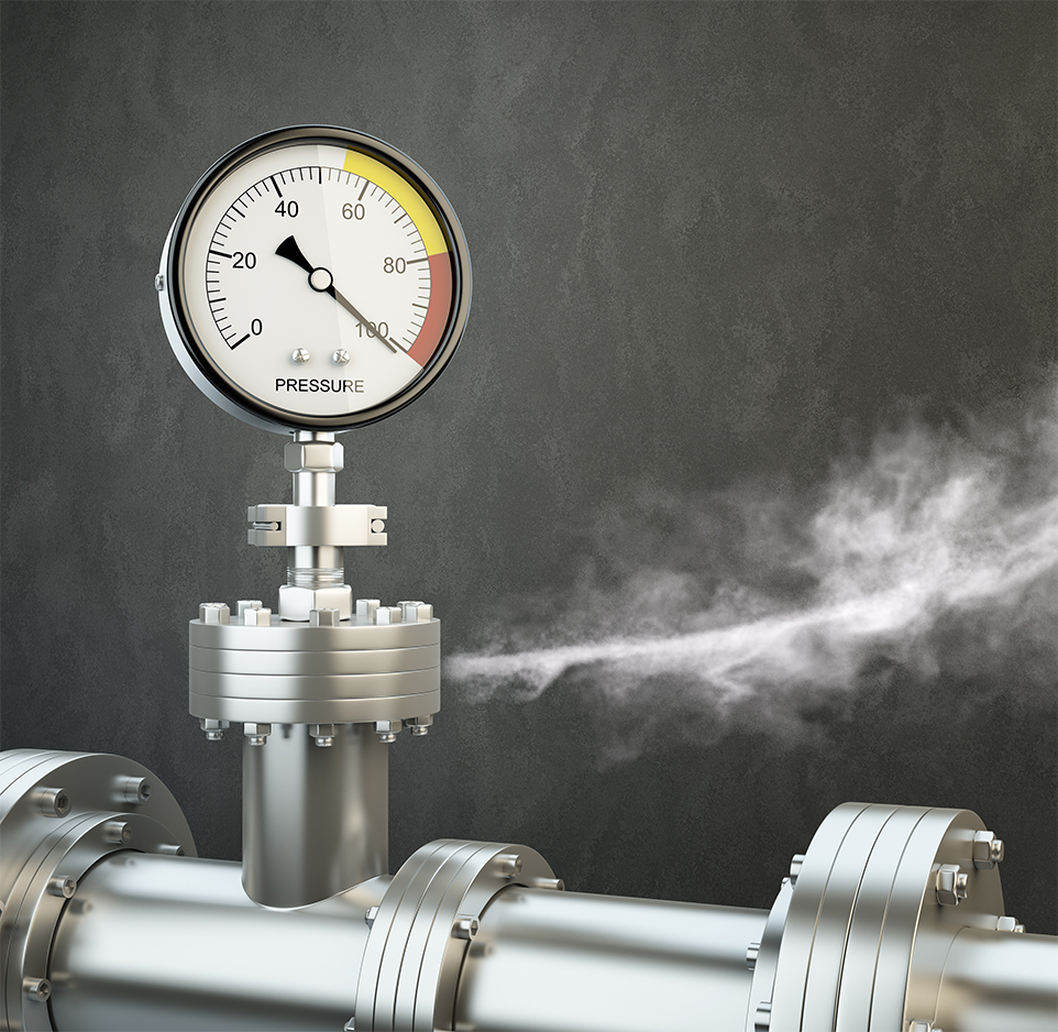
4. Continues System Monitor
The ProvenGas safety system constantly monitors the incoming gas pressure and will isolate the gas supply to the workshop / lab when the pressure falls below 12mbar.
Specification
ProvenGas Unit:
- Gas Supply Pressure: 20 – 60 mbar
- Compatibility: 1st 2nd and 3rd Family gasses
- Electrical Rating: 230V 50HZ 3 Amp Fused
- Construction: Control Panel & Transmitter ABS Enclosure
- Ambient Temp: 0° to 55°C
Air Pressure Switch:
- Range: 0.2 – 3 mbar
- Max Pressure: 50 mbar
- Pressure Connections: 6mm Push On
- Enclosure: IP54
Features
- CE Approved
- Comprises Control Panel, Pressure Transmitter and Air Pressure Switch
- Constantly monitors for low gas pressure
- Simple installation and commissioning; no complex volume or orifice plate calculations required
- Removable key switch for security
- Incorporates Emergency Cut-Off switch as standard
- Low power consumption
- Can be used on Natural Gas or LPG
- LED status indications
- Used with any EN161 Approved solenoid or
- Electro-Hydraulic shut off valve
- Connects into gas supply of safety shut off valve
Installation
A 3 amp fused spur must be used to provide the 230V required to power the panel. A safety shut-off valve (approved to EN161) is powered by the panel from terminals marked ‘valve’.
The pressure transmitter mounts directly onto the safety shut-off valve (downstream test point) and is wired back to the panel by two core low voltage cable. It should be connected to the low voltage terminals marked ‘pressure switch’. Remote emergency shut-off buttons can be connected to the panel’s low voltage terminals marked ‘emergency stop’. For large installations, the fill and prove times can be doubled simply by one position change of the dip switch.
The differential pressure switch is connected to the terminal marked ‘fan switch’. There is a 45 second time delay on the interlock to help prevent nuisance tripping when using differential pressure switches
